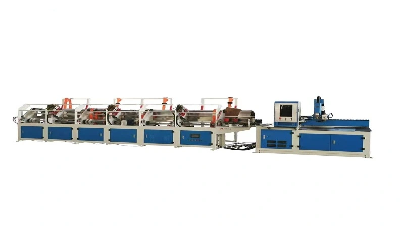
Pipe shrinking (swaging / necking) and pipe expanding (sizing) are two core cold‑end‑forming processes for metal tubular parts. Both deform only the pipe end without cutting chips, but they act in opposite deformation directions.
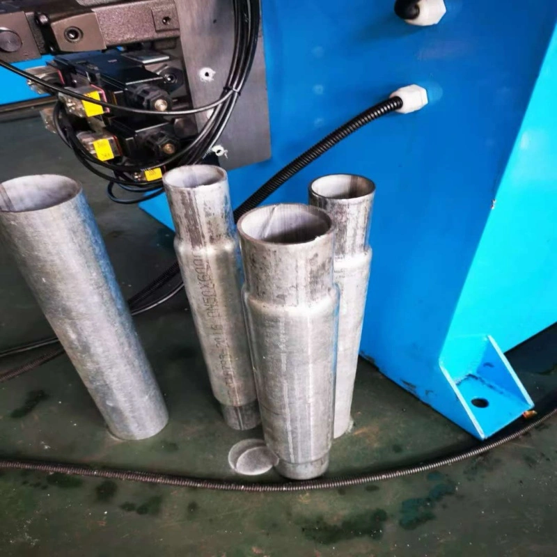
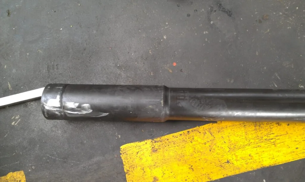
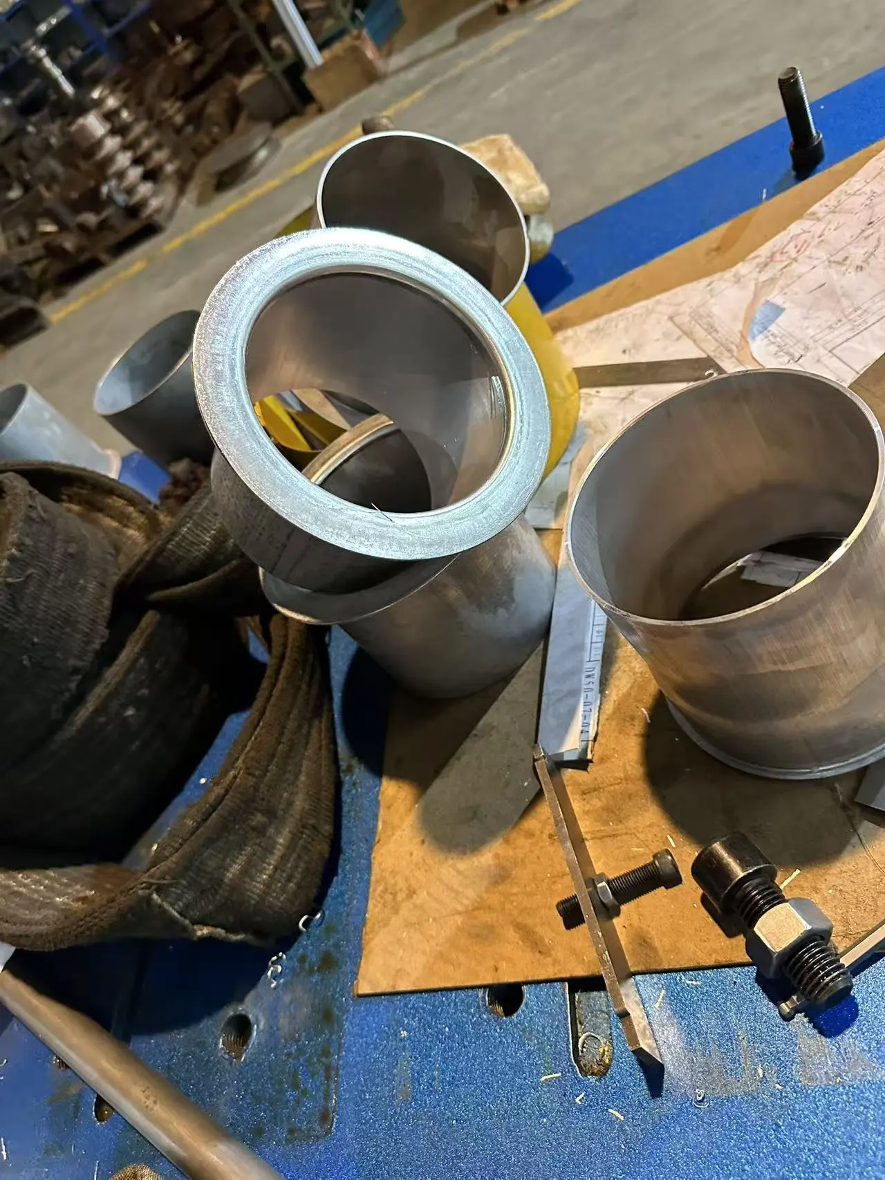
Pipe Shrinking: Photo set: raw tube end → finished reduced‑diameter sample; cross‑section sketch showing material compressed radially inward.
Pipe Expanding: Photo set: raw tube end → finished enlarged‑diameter sample; cross‑section sketch showing material stretched radially outward.
1. Pipe Shrinking (Swaging / Necking)
Definition: Radial compression force presses the pipe‑end material inward, reducing the outer and inner diameter of the tube end. Wall thickness normally increases slightly after cold compression.
Two common shrinking modes
Die‑press shrinking (stationary die swaging) Multiple‑segment closing dies squeeze the pipe end in one or several strokes. Suitable for short‑section necking, simple profile.
Rotary swaging (rotary hammer shrinking) Rotating hammers continuously hammer the pipe end for gradual reduction. Good for long tapered / conical necks.
Key features
✅ Wall thickness increases; material becomes stronger at the reduced section. ✅ Less risk of cracking; suitable for medium‑high carbon steel, alloy pipe. ❌ Easy to produce wrinkles if wall is too thin.
Typical applications
Telescopic tube assembly (small‑diameter male insert end)
Furniture legs, fitness equipment tubular parts
Nozzle transition joints, cable‑gland pipe ends
Pre‑step for tube‑end thread preparation
2. Pipe Expanding (Tube Sizing)
Definition: Mandrel / segmented expanding die pushes outward from inside the pipe end, stretching material radially to enlarge outer and inner diameter of the pipe tip. Wall thickness will decrease slightly due to tensile stretching.
Two common expanding modes
Solid‑mandrel expanding: Single solid punch pushes into tube end for simple straight enlarged mouth.
Segmented‑split‑die expanding: Multi‑petal die opens inside the tube. For larger deformation and non‑straight complex profiles.
Key features
✅ Realize female socket end for another pipe to insert into. ❌ Material is under tension; high risk of cracking if deformation ratio is too large. ❌ Thin‑wall tubes easily wrinkle or collapse without external support die.
Both shrinking and expanding belong to pipe‑end cold forming. Sharp burrs from tube cutting must be removed by chamfering before forming.
For heavy deformation, use multi‑station progressive forming instead of one‑shot stamping to avoid defects.
Both processes are normally performed before pipe bending, to avoid access obstruction of dies / mandrels on bent workpieces.
Sample recommendation: Submit real tube sample for trial‑forming to verify feasible deformation ratio before mass production.
FAQ — Pipe Shrinking VS Pipe Expanding
Q1: What is the fundamental difference between pipe shrinking and pipe expanding?
A: Pipe shrinking compresses tube‑end material inward to reduce diameter, wall thickens slightly. Pipe expanding stretches material outward to enlarge diameter, wall becomes thinner. Shrinking produces male insert end; expanding produces female socket end for tube‑to‑tube assembly.
Q2: Which process is more likely to crack during forming?
A: Pipe expanding. The tube end bears tensile stress when stretched outward. Too‑large single‑step expansion ratio will cause cracking. Shrinking works under compression stress; cracking seldom occurs, but thin‑wall pipes may wrinkle.
Q3: Can I do large‑diameter reduction or enlargement in one single stroke?
A: Not recommended. For heavy deformation, adopt multi‑station progressive forming. One‑shot large deformation will trigger wrinkling (shrinking) or cracking (expanding).
Q4: What tube end do I need for telescopic pipe set: shrinking or expanding?
A: One pipe end uses shrinking (male insert), the mating counterpart tube end uses expanding (female socket), so they can nest together.
Q5: Can both shrinking and expanding be done on the same tube‑end‑forming machine?
A: Yes. On multi‑station tube end former: install shrinking die for necking station and expanding mandrel for sizing station. One machine can finish both operations by changing stations / dies.
Q6: Is wall thickness changing unavoidable for shrinking / expanding?
A: Yes. Cold plastic deformation changes wall thickness. Shrinking makes wall thicker; expanding makes wall thinner. This thickness variation must be considered for subsequent assembly or threading.
Q7: Can I perform shrinking / expanding after pipe bending?
A: Technically possible but not preferred. After bending, the bent geometry may block die / mandrel access to tube opening. If you have to form after bending, custom special‑offset tooling is required. Best practice: end‑form first, then bend.
Q8: What pre‑treatment is mandatory before shrinking or expanding?
A: Cut tube to length, remove sharp burrs and complete inner & outer chamfer. Burrs will scratch dies and initiate crack points during cold deformation.
Q9: Which material is more suitable for expanding process?
A: Materials with good ductility: low‑carbon steel, aluminum, copper, soft stainless steel. High‑strength low‑ductility alloy is hard for expanding, easy to crack; better choose shrinking process if possible.
Q10: What defects may appear for shrinking process?
A: Main defects: end wrinkles, uneven necking dimension, tube‑end offset. Main causes: too thin wall, improper die closing speed, poor tube straightness.
Q11: What defects may appear for expanding process?
A: Main defects: tube‑end crack, wall local thinning collapse, out‑of‑round mouth. Main causes: excessive expansion ratio, poor material ductility, lack of auxiliary supporting die.
Q12: Can shrinking / expanding parts be automated with robot loading?
A: Yes. CNC multi‑station pipe‑end‑forming machine reserves signal‑handshake interface for robot loading‑unloading, can integrate with pipe‑bending & pipe‑cutting machines for full tube‑processing line.
Core Selection Criteria 1. Dimensions Before & After Forming Dimensional data of raw tube and finished tube end is the primary basis for model selection and die design. Key note: Excessive single‑step deformation will cause cracking or wrinkling. Heavy deformation requires multi‑station progressive forming. Suggestion: Prepare a 2D drawing marked with raw tube and finished end dimensions for manufacturer evaluation. 2. Number of Forming Stations Station quantity defines how many forming operations can be completed in one clamping cycle without manual die change. Tip: Select stations strictly according to your process flow; do not blindly purchase extra unused stations. 3….
Manual pipe cutters work well for small workshops handling low batch orders, while automatic pipe cutting systems are built to reduce manual handling for continuous production. Beyond cutting precision, operators also need to consider labour cost, workpiece consistency and changeover time when selecting equipment. 1. Core Definition Manual Pipe Cutting Machine Operators manually load tubes, adjust fixtures, set cutting length and trigger cutting one piece at a time. Simple structure, low investment, suitable for small batch or prototype jobs. Automatic Pipe Cutting Machine Equipped with automatic magazine feeding, servo length positioning, pneumatic/hydraulic auto clamping, continuous cutting and automatic unloading. Pre-set…
Overview Pipe cold sawing and fiber laser tube cutting are two mainstream pipe blanking solutions. Many buyers only compare machine purchase price, ignoring hidden secondary processing cost, precision stability and material loss. This article compares real precision and full-lifecycle cost for reference. 1. Working Principle Pipe Cold Sawing Mechanical shearing cutting via rotating carbide saw blade. It is designed for straight cut or simple fixed-angle bevel only. Fiber Laser Tube Cutting Non-contact thermal cutting. High-energy laser melts the metal, and assist gas blows away molten slag. It can complete cutting, hole, slot, cope, marking and bevel in one clamping. 2….